Aug 3, 2026
Designing the Carbora Labs Logo: My First CAD Project
Most logos only ever exist on screens.
I knew from the beginning that I didn't want that.
If Carbora Labs was going to be about building things, then its logo should be something I could actually hold. Something that could sit on my desk, spark conversations, and remind me why I started building in the first place.
So before anything else, I decided to design a physical logo.
The logo was the excuse
At the time, I had very little hands-on experience with CAD.
Like many developers, I'd watched plenty of videos, opened CAD software a few times, and then quietly closed it after feeling overwhelmed.
Instead of treating CAD as something I had to study, I gave myself a real project.
Build the Carbora Labs logo.
That single goal completely changed how I approached learning. Every sketch, every measurement, and every mistake had a purpose because they all moved me one step closer to something I genuinely wanted to own.
From sketches to solids
I started by designing the logo manually in Onshape.
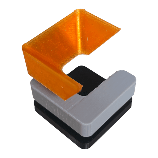
Once I was happy with the overall shape, I recreated it as three interlocking layers that could be 3D printed and assembled into a single object.
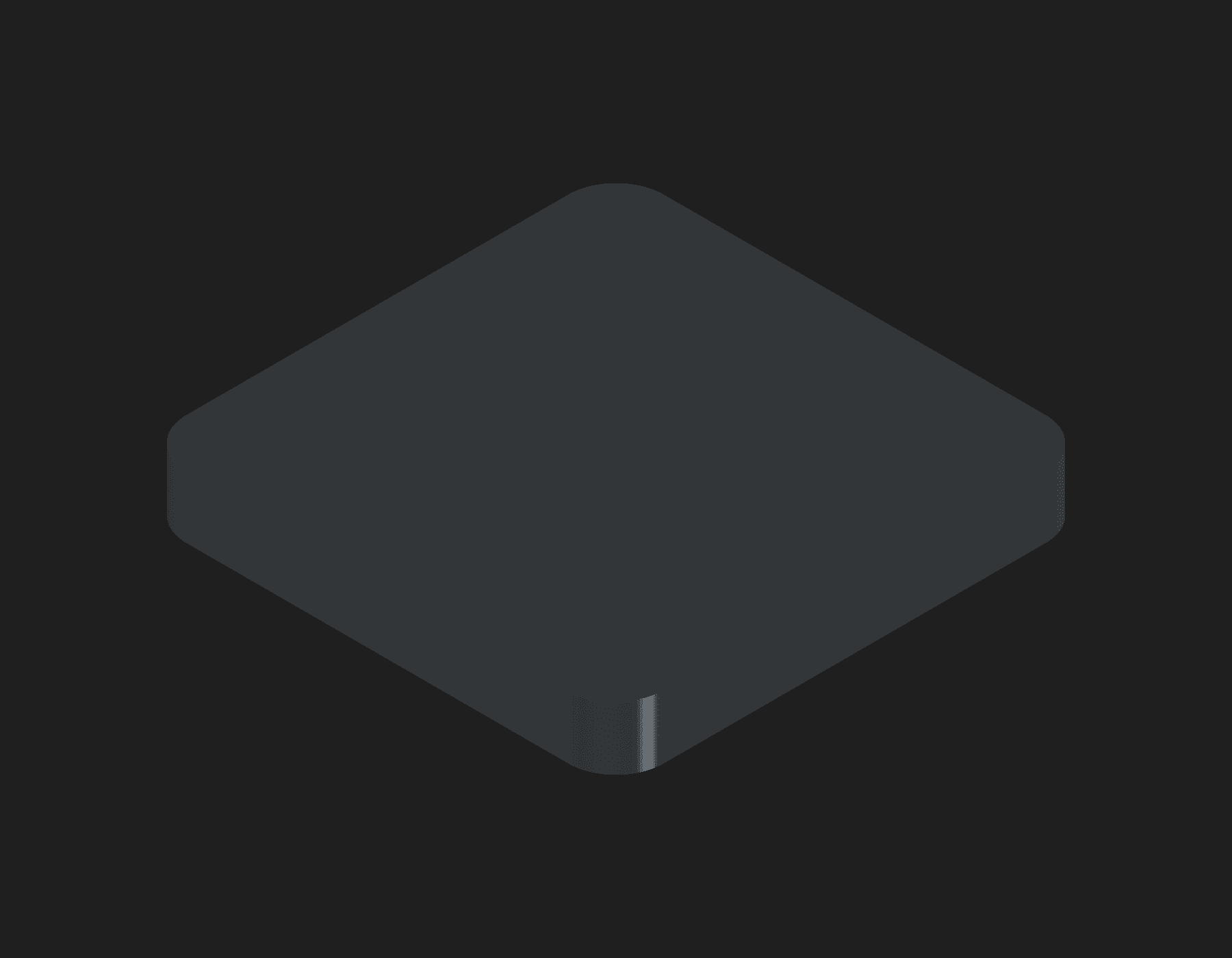
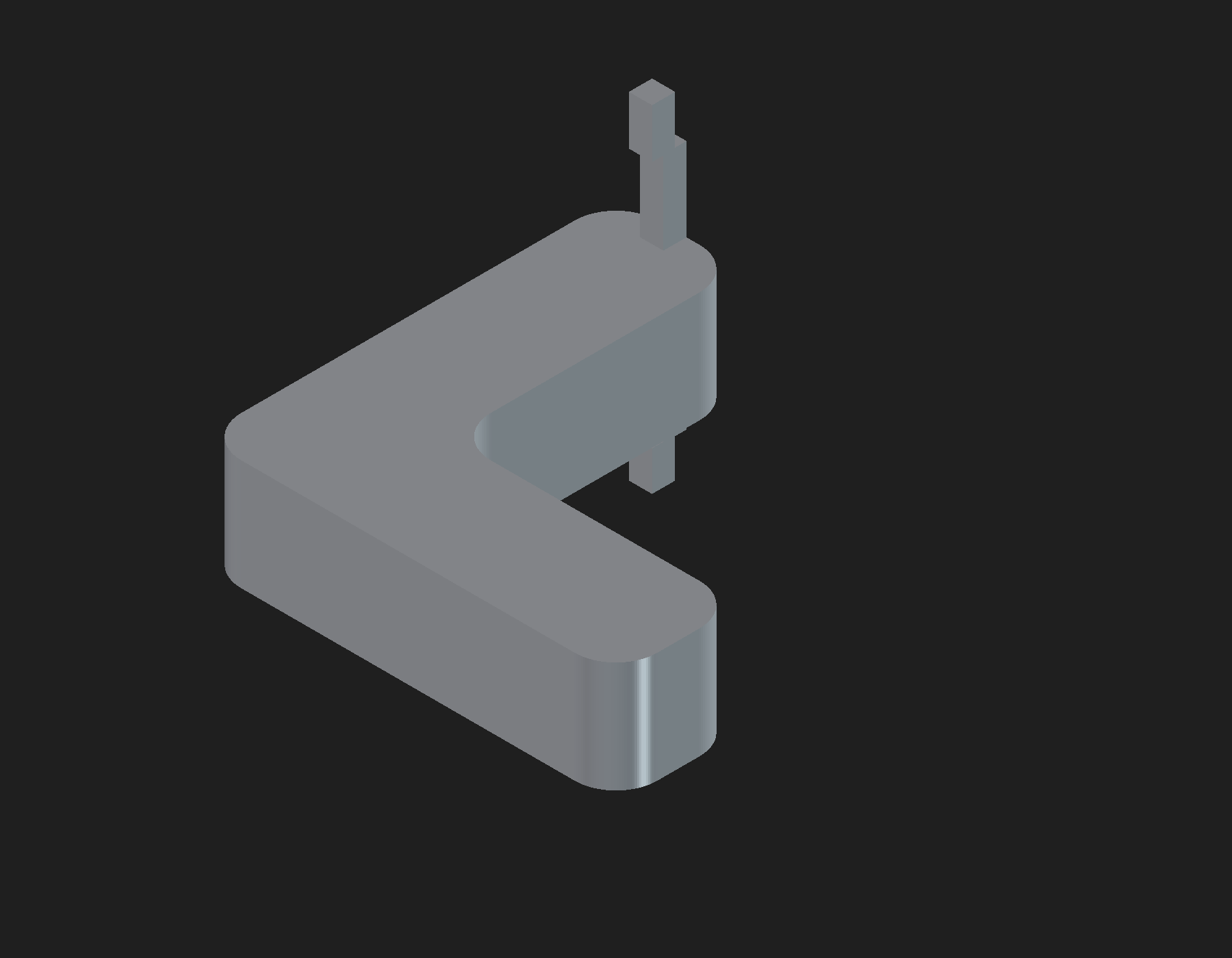
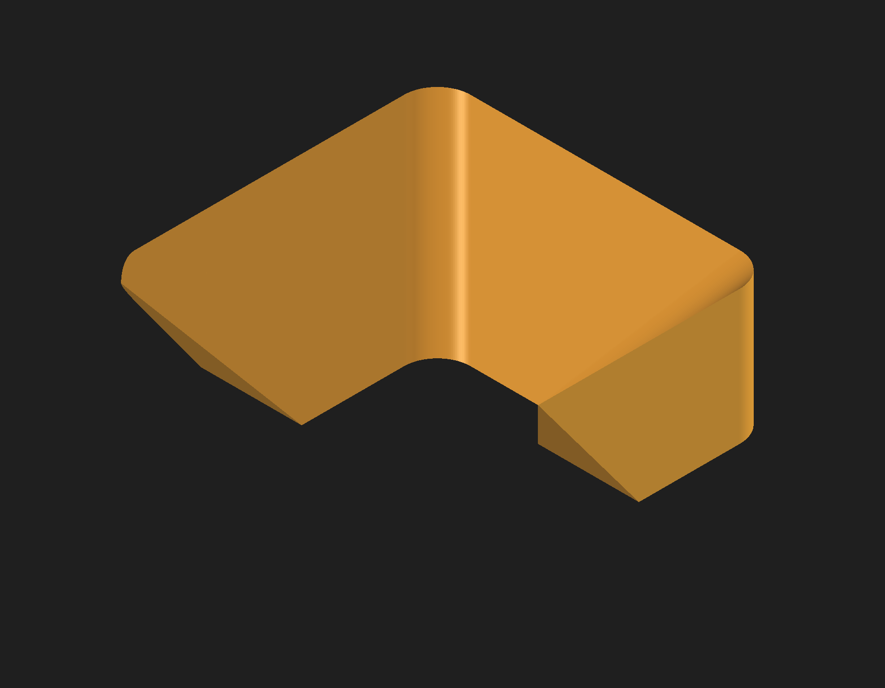
Just as I was about to spend hours figuring out some of the more advanced geometry, I came across something I hadn't expected: FreeCAD MCP.
After a bit of setup in Cursor...
...it just worked.
The experience was surprisingly similar to working with AI while programming. Instead of endlessly searching documentation, I could explain what I wanted, sketch ideas, point at geometry, and iterate naturally. It didn't replace learning CAD, but it made learning feel conversational.
That was one of the coolest parts of the entire project.

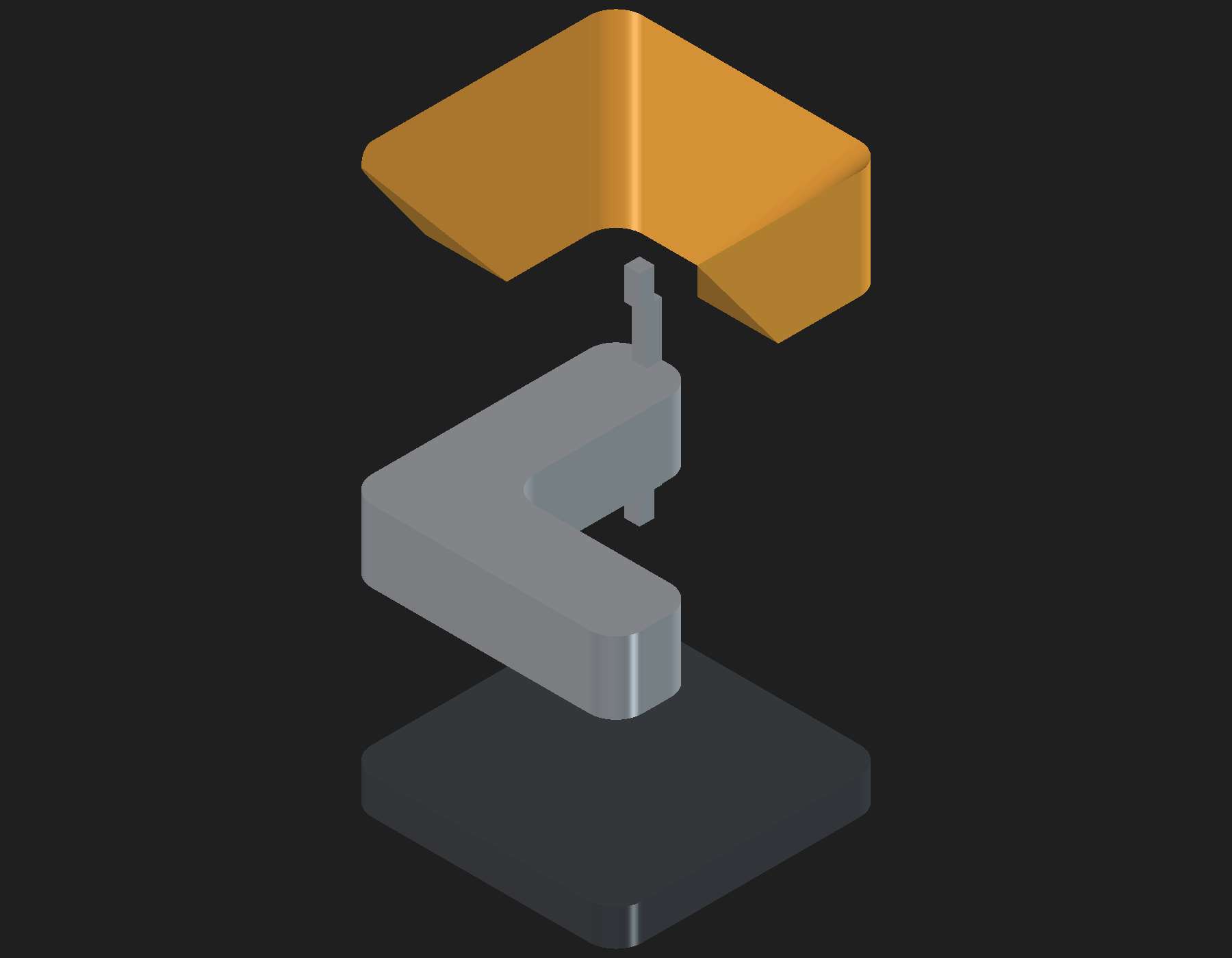
You can orbit the assembled solid yourself — this is the same FreeCAD model, exported as STL:
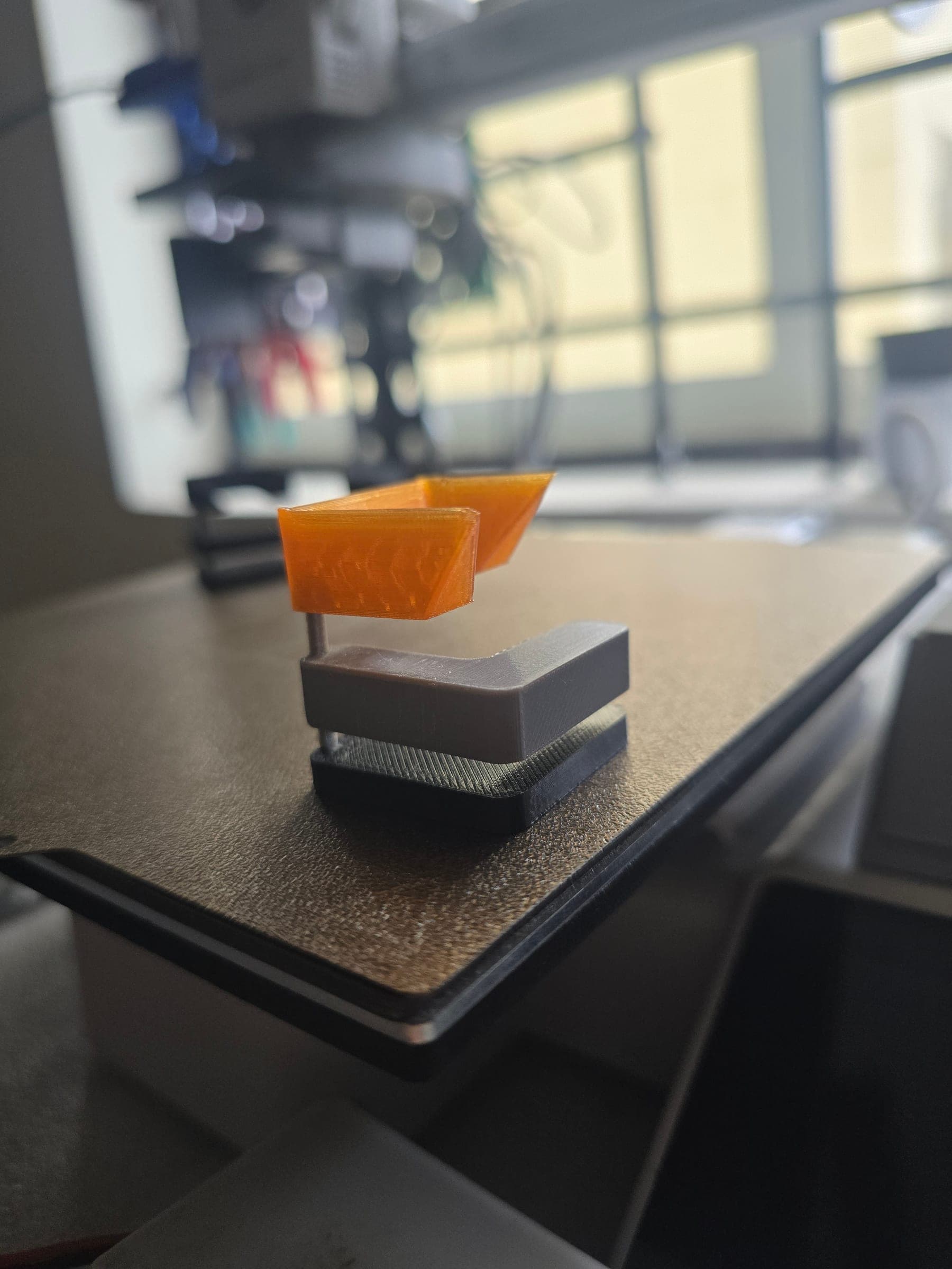
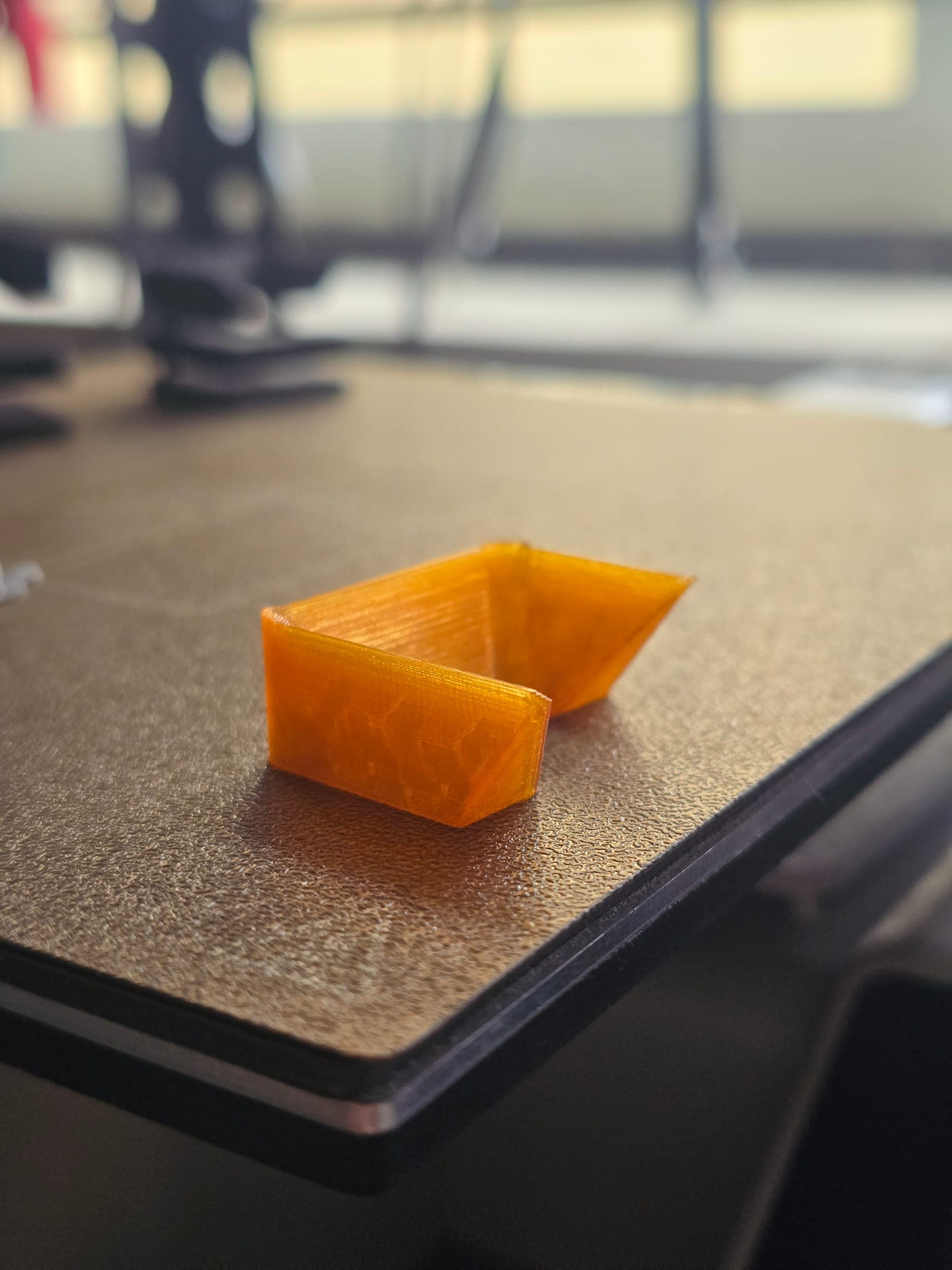
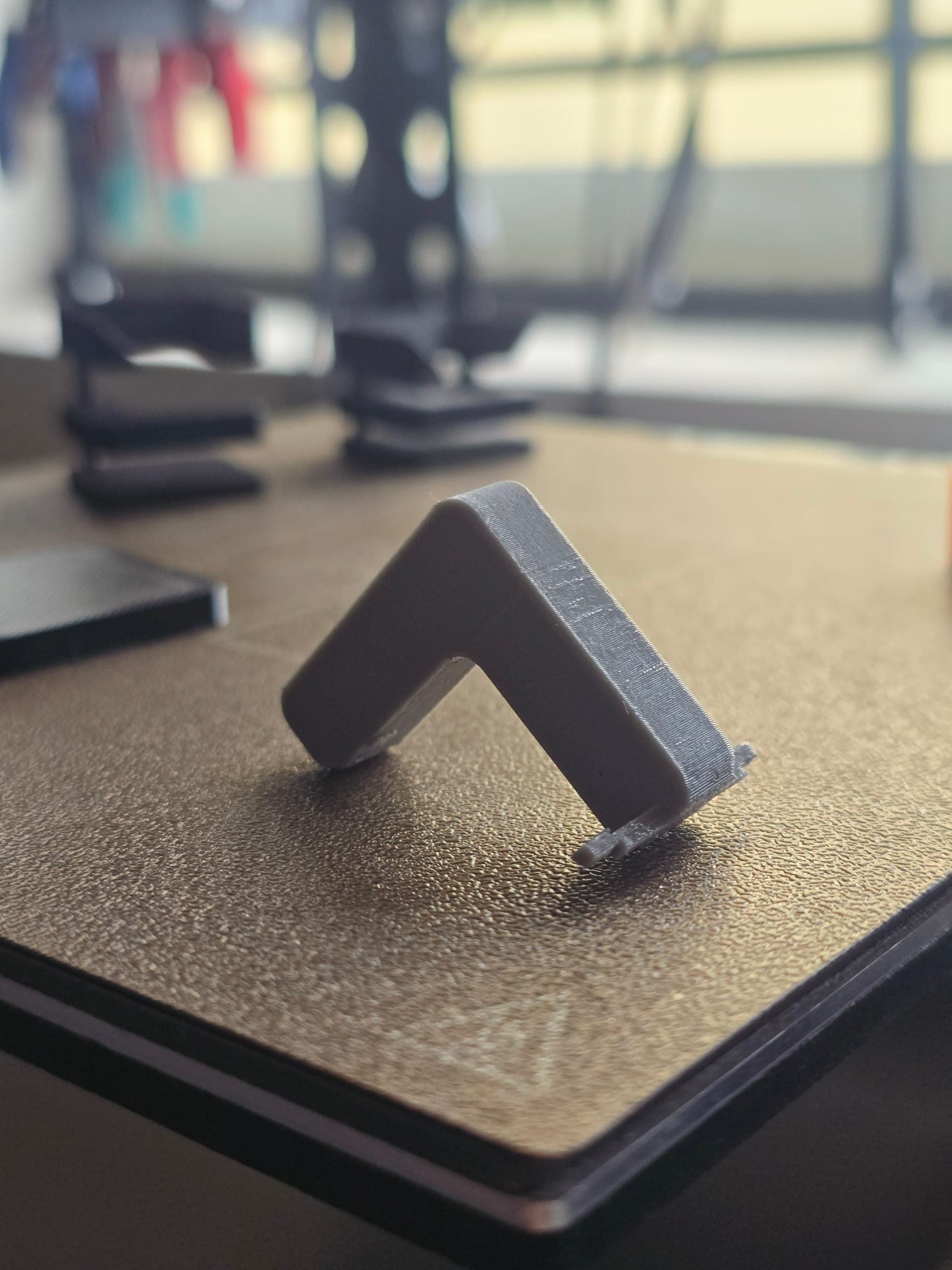
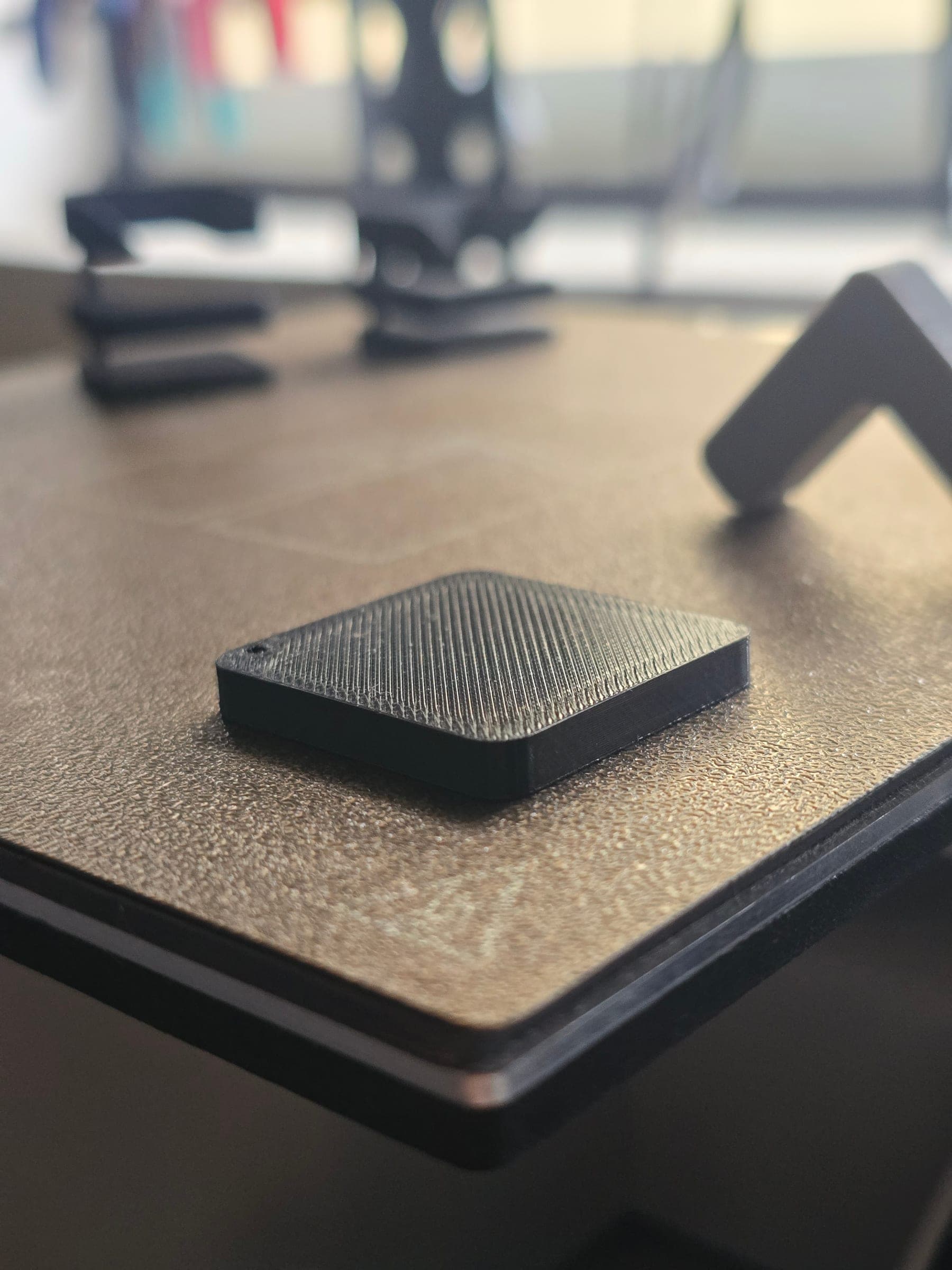
The printed parts looked like this once they left the printer:
CAD ends where reality begins
Getting the model to look right wasn't the hard part.
Getting the print to fit together was.
A perfect CAD model doesn't automatically become a perfect print. Plastic behaves differently. Holes print smaller. Pins print larger. Tiny tolerances that look fine on-screen suddenly become impossible to assemble.
That meant printing...
Adjusting...
Printing again...
And repeating the process until the physical object matched what I had imagined.
Those iterations taught me far more than any tutorial could.
More than just a logo
Holding the assembled logo for the first time felt almost unreal.
After days of learning, redesigning, and printing, it finally existed outside my monitor.
I absolutely love how it turned out.
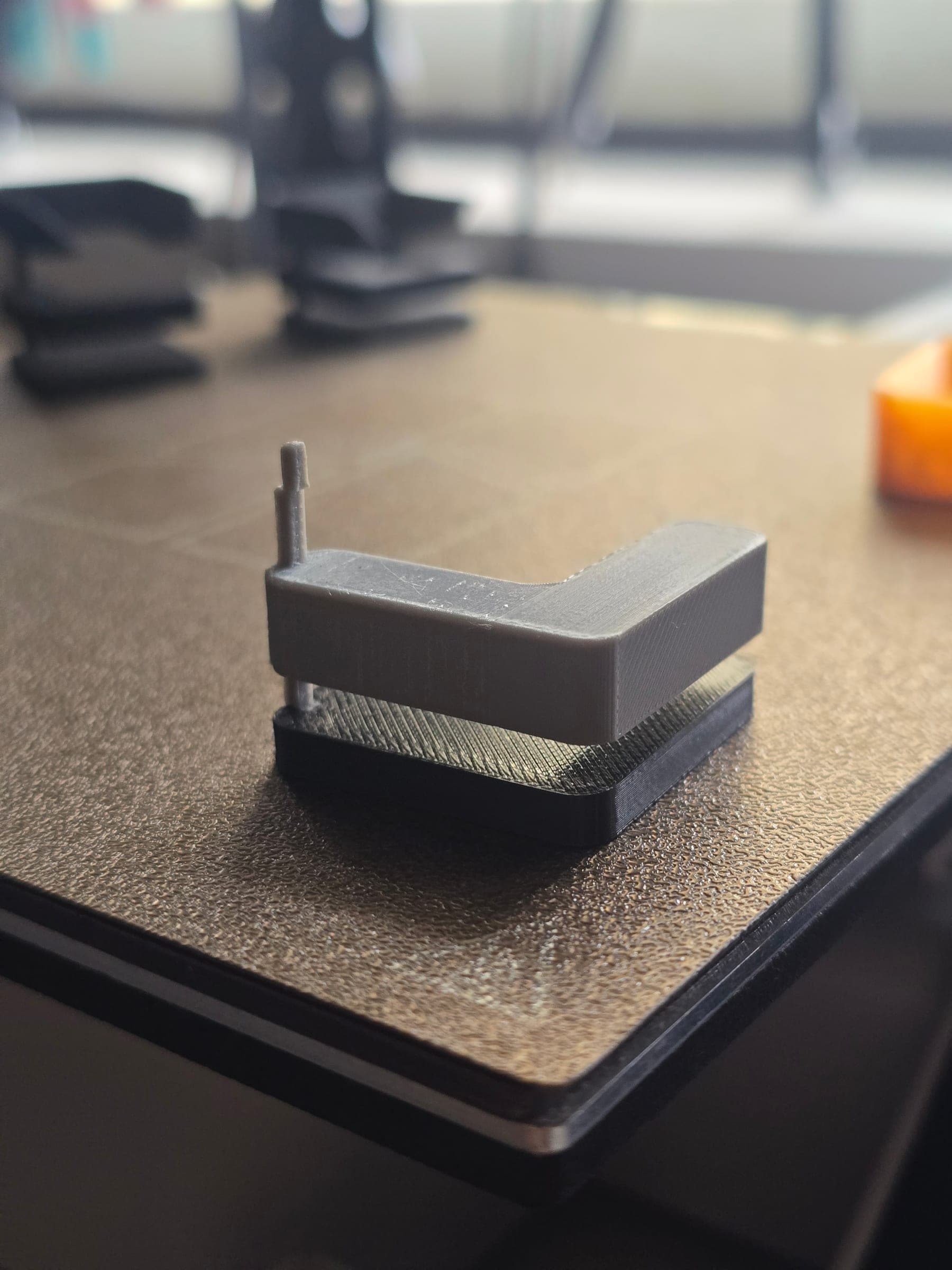
Seeing all three pieces fit together brought a huge smile to my face. It now sits on my desk exactly as I imagined it would, and I still find myself picking it up every now and then.
Looking back, the logo wasn't really the project.
It was the excuse.
By giving myself something I genuinely wanted to build, I accidentally learned the foundations of CAD, 3D printing, manufacturing tolerances, and AI-assisted design.
More importantly, opening a blank CAD workspace no longer feels intimidating.
Now, when I think of an idea, I know I can build it.
And I think that's a pretty good logo.